
Transformers and reactors are often treated as a single category when magnet wire is specified. In practice the duty is quite different: a distribution transformer is dominated by thermal and impulse considerations, a harmonic-filter reactor by current waveform, and a high-frequency inductor by skin effect and proximity loss.
Three short cases below show how those differences translate into a wire specification.
Case 1: Dry-Type Distribution Transformer
| Parameter | Value |
|---|---|
| Type | Dry-type, cast-resin insulated |
| Rating | 1,000 kVA class |
| Primary | Medium voltage |
| Winding | Copper round, layer wound |
| Duty | Continuous, with impulse events at switching |
| Cooling | AN / AF |
The dominant requirement here is thermal endurance coupled with the ability to withstand impulse voltage without breakdown at the winding ends. Two specification choices follow.
First, thermal class is set by the hot-spot temperature with the cooling class in use, and the wire class is chosen with margin above that figure — not at it. A cast-resin winding is difficult and expensive to repair, so the cost of moving one class higher is small against the cost of a failure.
Second, the insulation build must resist impulse stress at the ends of the winding, where the voltage distribution is non-uniform. Grade 2 build is the norm; for the first and last few layers, some designs specify a heavier build or an interleaved insulation arrangement. This is a design decision rather than a wire-only one, but the wire specification must be capable of supporting it.
Resulting specification: high-temperature polyester-imide or polyamide-imide construction on copper, grade 2 build, with breakdown voltage verified on the finished wire and the impulse withstand confirmed by the transformer designer's own test regime.
Case 2: Harmonic-Filter Reactor
| Parameter | Value |
|---|---|
| Type | Iron-core series reactor, harmonic filter |
| Duty | Continuous, with significant harmonic current content |
| Winding | Copper round, multi-layer |
| Cooling | Natural air |
| Design issue | Higher RMS current than the fundamental suggests |
The trap in a filter reactor is the current waveform. The fundamental current sets the nameplate figure, but the harmonic content raises the true RMS current and creates additional losses at frequencies well above the fundamental. The winding runs hotter than a sinusoidal design of the same nominal current.
The specification response is twofold. Thermal class moves up to cover the actual temperature reached under the harmonic load, not the nominal one. And the designer must account for the additional AC loss in the conductor, which can be significant in a multi-layer winding where proximity effect is strong.
Resulting specification: a high-temperature build, with the thermal class selected against the measured hot-spot temperature under real harmonic load. Where the AC loss is a substantial fraction of total loss, the designer may also move to a smaller conductor in parallel or a flat conductor — a design change that the wire supply has to be able to support.
Case 3: High-Frequency Inductor
| Parameter | Value |
|---|---|
| Type | High-frequency inductor, power conversion |
| Frequency | Tens of kHz |
| Winding | Copper, multi-strand |
| Cooling | Forced air |
| Design issue | Skin effect drives up AC resistance |
At tens of kilohertz, current concentrates in the outer layer of the conductor. A solid wire of the right DC cross-section will have a much higher effective AC resistance, and the loss becomes heat in a winding with limited surface area to dissipate it.
The standard answer is to use multiple strands of finer wire in parallel, so that each strand is small relative to the skin depth. This changes the wire requirement in two ways: the individual strand diameter becomes a specified parameter rather than a convenience, and the number of strands and the twist or bundle construction become part of the specification.
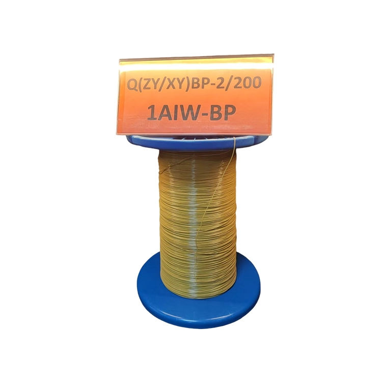
Resulting specification: a self-bonding or conventional enameled build in fine strands, with strand diameter selected against the operating frequency and current. Where the strands must be held together through winding and operation, a self-bonding construction removes the separate impregnation step.
Comparison of the Three Cases
| Case | Dominant constraint | Thermal class | Key wire properties |
|---|---|---|---|
| Distribution transformer | Thermal endurance, impulse withstand | High, with margin | Breakdown voltage, adhesion, build consistency |
| Harmonic-filter reactor | True RMS current from harmonics | Elevated for actual hot spot | Thermal class, low AC loss behaviour |
| High-frequency inductor | Skin and proximity effect | Moderate, driven by forced cooling | Strand diameter, self-bonding option |
The pattern is that the wire specification follows from the loss mechanism, which in turn follows from the waveform. Reactive components are not interchangeable, and a specification carried over from one type to another is a common source of overheating.
Practical Checklist for Reactive Component Winding
- Establish the true RMS current and the harmonic spectrum before calculating winding loss.
- Determine the hot-spot temperature, not the average winding temperature, and choose thermal class with margin above it.
- For multilayer windings, quantify the AC loss contribution — proximity effect is often underestimated.
- Where frequency is high, specify strand diameter explicitly rather than inheriting it.
- For cast-resin and other hard-to-repair designs, take the additional thermal margin.
- Verify breakdown voltage and adhesion on the finished wire, and confirm the winding process does not degrade them.
A reactive component is thermally a more demanding environment than its nameplate suggests. The specification work is done at design stage, and it is considerably cheaper there than in the field.
Winding transformers or reactors? Share the type, current waveform, frequency, hot-spot temperature and winding construction. We will recommend the thermal class, conductor form and insulation build — and supply the breakdown voltage and thermal-class evidence to support the design.